Sedron Internship: Punch Redesign
Skills: [NX, Mechanical Design, Engineering Drawings, GD&T]

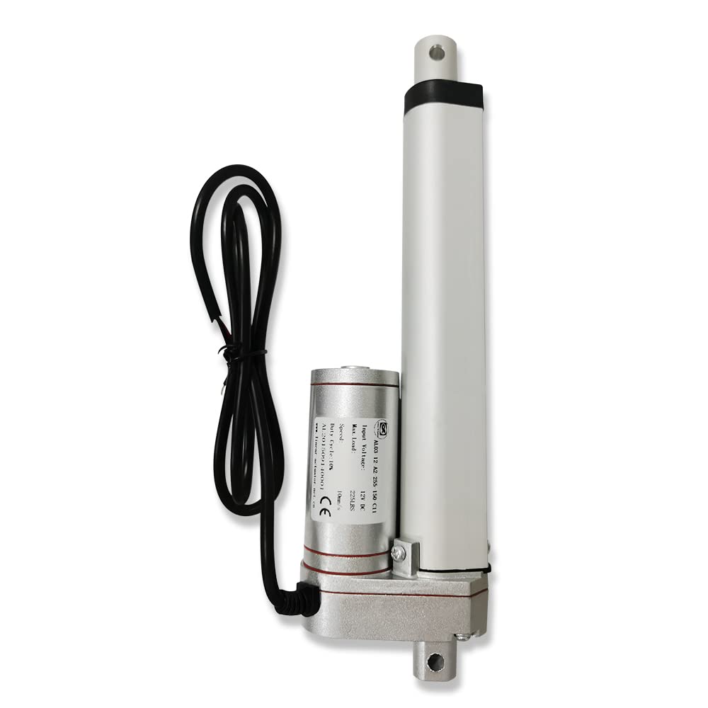
The purpose of this project was to design an improved punch for one of Sedron's active projects. The punch was driven by a linear actuator, similar to the one shown above, that would push the punch into a sealed chamber and pelletize pieces of dried sewage material. These pellets would then fall into an auger to be transported to the next step in the process. The primary goal of the redesign was to increase the diameter of the punch to reduce blockages, but having observed this part in action before I identified a couple other common issues that could be resolved. One of these was that small pieces of dried material would build up on the punch shaft and harden. These hard deposits could then push past the shaft seal and tear up the bushing, something that I had seen happen once before and that was difficult to repair. Another problem I saw was that the punch and the hole it was pushing the dried material through weren't lined up properly, which meant that during every punch cycle it was possible to hear the punch clip the edge of this hole before passing through it. I addressed all of these problems in my redesign.

Increasing the shaft diameter was the most straightforward part of this project. Because of size constraints, I had to find a thinner bushing that the one we had used previously. To better protect the bushing, I changed the sealing mechanism from a shaft seal to a rod wiper seal. Since the difference in pressure between the pressurized volume and ambient was on the order of 5-10 millibar, I decided that the wiping action of the seal was more critical than the sealing action. This change required some fairly major redesign of the seal housing. Finally, I increased the diameter of the dry material hole to be larger than the shaft to eliminate the clipping issue. I found a tight clearance was unnecessary for this part, so this design change was fairly simple to make. After several meetings discussing the design with my manager and the principal technician for the project, my changes were approved. I updated the engineering drawings, using the GD&T system to define tolerances.